For almost as long as I have been using wireless networks, I have had a nagging problem. It’s not a complicated problem. I want to move data across a network to wired devices. Admittedly, it is always best to run a cable and connect multiple devices to a switch. The problem with this solution is usually architecture and aesthetics. Running a line through walls is best left to a professional, and if not done during the construction of the building can quickly become an expensive project. It may be possible to simply hang a cable or run it across the floor, but going through doors and walkways can make this a nonviable option.
The answer to these problems is a wireless bridge, but until a few years ago, I struggled to find something that worked. First, I had a Buffalo router flashed with DD-WRT running WPS. Better than nothing, but it required a complicated configuration that proved unreliable. Later I tried a Linksys Media Bridge. I hoped my troubles were over. After all, this wasn’t a hack running on custom firmware but a device from one of the most reputable vendors, explicitly designed for this use case. It was easy to configure, but the machine was buggy, freezing up and requiring a power cycle to start working again. This often happened, and it became a daily ritual to reboot the device before bed. The next device to disappoint me was an ASUS range extender/bridge system. I didn’t want the range extender functionality since the signal strength was acceptable, but that was easy to disable. This device worked for about a year, but the speeds were poor. Despite being an 802.11 ac device connecting to a high-quality Unifi access point, I could never get more than 50-80mbps even in the same room.
Then I discovered the fantastic Latvian network manufacturer Mikrotik. Using their highly flexible RouterOS combined with a wide selection of hardware, it possible to create a bulletproof wireless bridge and move data almost anywhere with no cables needed.
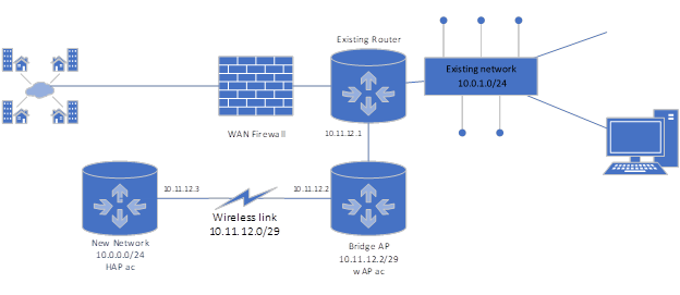
In the following example, we will assume an existing network with the IP space 10.0.1.0/24, and we will want to create a remote network of 10.0.0.0/24. We will configure two new devices and add both a transport network and the new destination network.
Let’s go over the basic setup for this application. We will need two Mikrotik wireless devices to establish a point-to-point link. In this example, we will be using a wAP ac and an hAP ac. The first device will be the access point and the second the station. The second device will also provide the wired connections for the remote network, so we use the hAP as it has 5 ethernet ports.
Here is a basic diagram of the setup:
 It is always best to remove any existing configuration using the reset configuration option in the system menu. Make sure to check the box for no default configuration to ensure that we are starting clean. The device will reboot, and all configurations are now removed.
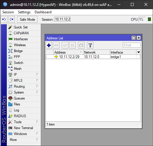
At this point, the device will have no IP address and need to be accessed via the MAC address using Mikrotik’s WinBox program. Upon connection, follow the prompt and set a new password; with that done, navigate to the bridge menu. Here we will add all ethernet ports into the default bridge. Then go to the IP menu and open addresses. Add an address here to the default bridge. Do not use an address that is in your existing IP subnet. We will want to use routing to direct packets, and so we will need a transport IP network. This will only need a few IPs, so use a small subnet like a /29. In this example, we will be using 10.11.12.0/29 for transport. In this case, assign 10.11.12.2 to the bridge for our access point. Here you might ask why we do not use the .1 address, and this is because we need an IP for the source and destination networks.
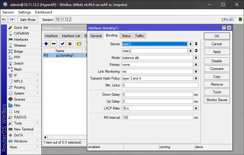
 Your WinBox session will be disconnected after this, but you can reconnect either with the MAC or to the IP address we just set if we add the network information to the interface we are connecting from. The next step is to establish a bonding interface to aggregate the 2.4 and 5ghz networks. Open the interfaces menu, click the + to create a new interface, and select bonding from the drop-down. Select WLAN 1 and WLAN 2 as the slaves. Set the mode to balance alb for best performance. Link monitoring should be set to mii. Now go back to the bridge menu and add this new bonding interface to the default bridge.
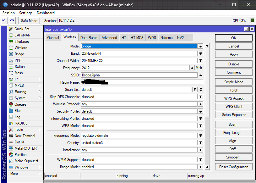
 The final step on the access point device is to set up the wireless links. First, set up a security profile. Here we can reuse the default profile but for security, check WPA2 PSK and then check the aesc cm boxes for the ciphers used. Enter a password in the preshared key field, click OK, and return to the wifi interfaces tab. Here select WLAN 1. This is a point-to-point connection, so the mode will be set to bridge. Don’t forget to set the SSID. Now duplicate these settings on the wlan2 interface to complete the wireless setup.
 Setup on the hAP ac will be similar but not identical. The first change is that we will want to make 2 bridges. The first bridge will be for the transport network, and the second will be for the destination network. Add the IPs to the two new bridges you just created. In this example, the first bridge will be 10.11.12.3, and the IP for our destination network is 10.0.0.1/24. Create a bonding interface containing both WLANs, add it to the first bridge, and add all ethernet ports to the second bridge. Configuration of the wireless interfaces is identical except now choose the mode “station bridge.” If everything is working, you will see this device connected to the previously configured access point.
Now we have a wireless link up, but we need to add a few routes to make everything work to get traffic to travel. We will add the IP address 10.11.12.1/29 to an accessible interface on the existing router. Next, open routes from the IP menu and click + to add a route of 10.0.0.0/24. The gateway is the IP address of the remote bridge device, in this case, 10.11.12.3. This is all the setup needed for the router on the original network.
The access point device will need only a single route configured. Set up 0.0.0.0/0 as reachable on bridge 1. Since all traffic goes through this bridge, and both 10.11.12.0/29 and the 10.0.0.0/24 networks are reachable, no other configuration is needed.
The remote station device will need a single default route of 0.0.0.0/0 with the gateway of 10.11.12.1. Once these routes are completed, any devices on the original 10.0.1.0/24 network can communicate with the new network at 10.0.0.0/24, and devices on that new network can access the internet.
While this setup may not provide a full gigabit of bandwidth, it has proven to be capable of several hundred megabytes in testing with no dropping or freezing.
There are a few other things to consider before deploying this setup. The new network of 10.0.0.1 is a separate subnet and so will need to have a DHCP server configured if you want any client devices to use it. Also, layer 2 protocols will not work across the link, so things like Apple Airplay and device discovery will not work without additional configuration. Please use the contact page for consulting regarding design and troubleshooting if you have any questions.